PROSTHESIS VESTIBULAR WITH TECHNOLOGY (MEMS)
Patents for licensing
A vestibular prosthesis includes micro-electric-mechanical (MEMS) sensors, gyroscopes in each sensitivity axis (X, Y, Z), accelerometers in each sensitivity axis (X, Y, Z) to detect an angular and linear movement providing displacement measurements, gyroscopes in each one of the spatial axes (X, Y, Z), a microprocessor connected to the MEMS sensors and producing an electric pulse pattern or a continuous galvanic current pattern, a conditioning unit that amplifies and conditions the microprocessor output to apply current to the stimulation electrodes, the microcontroller being configured to determine the displacement of the cupula and the otolithic mass, determine a membrane potential as a result of a displacement detected by the MEMS sensors by means of determining a transduction current, and determine an action potential discharge pattern for the primary afferent neuron,; which synapses with the hair cell by means of a mathematical model of the informative process of the vestibular mechanoreceptor.

DETAILED DESCRIPTION OF THE INVENTION
[0048] The various example aspects of the present invention are described in more detail below, referring to the drawings (figures, schemes and graphs) attached, in which the variations and the aspects of the present invention are shown. The various example aspects of the present invention may, however, be carried out in many different ways and should not be interpreted as limitations to the variations established in aspects of the present invention; on the contrary, the variations are provided so that this description is complete in the illustrative implementations and the scope of the same is fully transmitted to the experts in the technique.
[0049] Unless otherwise defined, all the technical and scientific terms used in this document have the same meaning as normally understood by an expert in the art to which the aspects of the present invention belong. The apparatuses, systems and examples provided in this document are illustrative only and do not intend to be limiting.
[0050] To the extent that the mathematical models are able to reproduce the magnitudes reported in the experiments, they can still be considered to model diverse natural processes. Therefore, a model for the vestibular function incorporated to a vestibular prosthesis in considered in this invention.
[0051] Various aspects of the present invention describe a simulation of the informative process of the vestibular function by means of a data microprocessor configured to develop/reproduce a mathematical model and its application as a vestibular function simulator in the stabilization process of the vertical posture, and the manner in which to use this model for its application in a vestibular prosthesis is described.
[0052] Various aspects of the present invention include a vestibular prosthesis that is helpful for people who suffer peripheral vestibular disorders and that may suffer incontrollable falls. The vestibular prosthesis of aspects of the present invention is a device that transforms a mechanical stimulus (the head's acceleration) into a group of electric signals with which the vestibular pathways are stimulated, whether directly (mode 1—invasive implantation) or through superficial electrodes (mode 2—galvanic stimulation).
[0053] The device of aspects of the present invention uses a high-level processing based on a neuromimetic model of the vestibular function. This model has been developed by imitating the functions of the natural organ and consists of a mathematical system of differential equations, which is in charge of converting the micro-electric-mechanical (MEMS) sensor output into electrical impulse patterns (mode 1, pulse-based stimulation) or DC voltage variation patterns (mode 2, galvanic current-based stimulation) in the form (amplitude, frequency and temporal modulation) of the vestibular organ's natural response to similar stimuli and that stimulates the vestibular system by imitating the natural function of said system.
[0054] According to aspects of the present invention, the MEMS sensors may be used as electromechanical analogue sensors of the natural vestibular sensors, and may include microgyroscopes that detect angular movements in order to carry out an identical function than the one carried out by the semicircular canals, and micro-accelerometers that detect static linear acceleration due to the gravitational pull, and the apparent linear acceleration in an analogous fashion as the otolithic organs, that is to say, the saccule and the utricle.
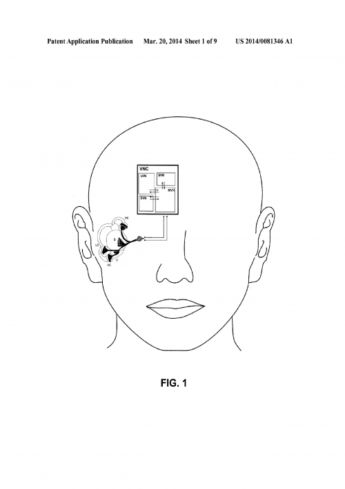
[0055] According to an example embodiment of the invention, the MEMS sensors can be placed behind the auricle or in the upper part of the head, whether bilaterally or unilaterally, in order to detect the acceleration the head is subjected to (at rest or in movement, during this process the person might be subject to falling situations, such as, for example, a trip or a shove). The information (acceleration data) obtained from these sensors constitutes an input (mechanical stimulus) for the vestibular function model.
[0056] The vestibular prosthesis of aspects of the present invention includes a microprocessor that uses the mathematical model of the vestibular function (see FIG. 3), which reproduces the informative process at the semicircular canals and the saccule from the movement in which they detect a mechanical stimulus (the head's accelerated movement) until the generation of action potentials per each afferent neuron in each vestibular sensor. This model simulates the natural vestibular function in the stabilization process of the vertical posture before a mechanical stimulus that could cause a fall, thus obtaining the action potential generation frequency constituting the electric signal integrated to the brain to generate the postural reflexes contributing to the preservation of the vertical posture by means of said stimulus.
Mathematical Model of the Vestibular Function and its Technical Implementation
[0057] The mathematical model of the vestibular function describes the informative process from the very moment when the vestibular organ detects a mechanical stimulus until the activation of the vestibular afferent nerves that take the information related to said mechanical stimulus to the brain.
[0058] Unlike other inventions, the model of aspects of the present invention is a neuromimetic model. That is to say, its design is based on the physiological processes that take place in the vestibular system naturally. In fact, the model is based on the results of basic research carried out and published, in its majority, by researchers from BUAP's Physiology Institute.
[0059] The present model is characterized in that it is a model formed by several steps, whose activity is determined by the functional interaction of five different steps, which are illustrated below:
[0000]
TABLE 1
General scheme of the mathematical model of the vestibular function.
[mathematical formula]
(1) � 2 � x � x 2 + 1 τ 1 � � x � t + 1 τ 1 � τ 2 � x = R 1 k 1 2 � ( 1 + l 1 L 1 ) � � ω � t Mechanical coupling at a vertical semicircular canal
[mathematical formula]
M + � 2 � X � X 2 + K e � � X � t + K c � X = M - ( G - W ) x Mechanical coupling at the saccule
[mathematical formula]
(2) I Tr = g Tr � ( x , s ) � ( V 1 - E Tr ) ; g Tr = g Tr � p � ( x , s ) ; p � ( x , s ) = 1 1 + e x + s - x 0 s 1 Mechanoelectrical transduction
[mathematical formula]
(3) C m � � 1 � � V 1 � t = - I Tr - I T - I L � � 1 I T = g T � m 3 � ( h 1 + h 2 ) � ( V 1 - E T ) I L = g L � V 1 τ m � ( V 1 ) � � m � t = ( m ST � ( V 1 ) - m ) � Q 10 τ h � � 1 � ( V 1 ) � � h 1 � t = ( q 1 � h ST � ( V 1 ) - h 1 ) � Q 10 τ h � � 2 � ( V 1 ) � � h 2 � t = ( q 2 � h ST � ( V 1 ) - h 2 ) � Q 10 Dynamics of the hair cell's membrane potential
(4) I Syn = φ(V 1) Synaptic Transmission
[mathematical formula]
(5) Cm 2 � � V 2 � t = I Syn - I Na - I K - I L � � 2 I Na = g Na max � ( m ∞ � ( V 2 ) ) 3 � ( C � ( V 2 ) - n ) � ( V 2 - V Na ) I K = g K max � n 4 � h K � ( V 2 - V K ) I L � � 2 = g L � � 2 max � ( V 2 - V L ) τ n � ( V 2 ) � � n � t = ( n ∞ � ( V 2 ) - n ) � Q 10 τ h � ( V 2 ) � � h � t = ( h ∞ � ( V 2 ) - h ) � Q 10 Dynamics of the primary afferent nerve cell's membrane potential
In which:
[0060] Step 1. Relates to the dynamics of the mechanical coupling of the cupula-endolymphatic system and the model of the otolithic mass that simulate the vestibular function in the semicircular canals and the otolithic organs respectively;
[0061] Step 2. Relates to the mechanoelectrical transduction mechanism in the hair cell;
[0062] Step 3. Relates to the dynamics of the membrane potential in the hair cell;
[0063] Step 4. Relates to synaptic transmission; and
[0064] Step 5. Relates to the dynamics of the membrane potential of the primary afferent nerve cell, the activation of the bipolar afferent neuron and the generation of action potentials.
[0065] These steps and their anatomical equivalent in the vestibular system are illustrated in FIGS. 2 and 4.
[0066] The vestibular mechanoreceptor model's input is the mechanical coupling of is the cupula-endolymphatic system and the otolithic mass model (step 1), which stimulate the vestibular function at the semicircular canals and at the saccule, respectively.
[0067] In order to develop the neuromimetic model, a set of differential equations describing the behaviour of the system in mathematical and physical terms in detail has been elaborated. Subsequently, a set of mathematical simplifications has been developed so that real instead of theoretical solutions are obtained for the natural input to the vestibule, represented by the linear and angular acceleration the head is subjected to. The present model is helpful from a technical point of view because it can be quickly solved—online—by a standard RISC (reduced instruction set) merchant microprocessor.
[0068] This technical solution of a highly sophisticated neuromimetic model in real time is a contribution of aspects of this invention because it allows processing stimuli in the form of the angular and linear acceleration detected by the accelerometers and the gyroscopes “in real time” and generating an output in the form of electrical impulse patterns (mode 1, pulse-based stimulation) or DC voltage variation patterns (mode 2, galvanic current-based stimulation) in the form (frequency and temporal modulation) of the vestibular organ's natural response to similar stimuli.
[0069] In the subjects to which the prosthesis is applied, the activity patterns of the vestibular prosthesis generated in this manner will produce an activity of the vestibular nerve similar to that naturally produced by such stimuli, effectively reproducing the response of the vestibular organ.
[0070] This example model is able to describe/reproduce the informative process at the peripheral vestibular system during the vertical posture stabilization process to in extreme situations (that could cause a fall) in the sagittal plane. See FIG. 4 and Table 1.
[0071] The output information of this model is a set of electrical impulses (V 2) with different frequencies, amplitudes and variable polarities, or the modulation of the galvanic current's amplitude, polarity and frequency, which depend on the intensity of the stimulus. In the natural organs, the frequencies with which the signals are sent through the vestibular pathways towards the brain determine posture control. The frequency of the appearance of these pulses is calculated with the help of the vestibular function model for a given stimulus, thus obtaining the information required by the brain to detect the angular and linear acceleration the head is subjected to and to generate the necessary reflexes to control posture. FIGS. 1, 2 and 4 and Table 1 show a general scheme of the vestibule and the equations used for the development of the mathematical model of each one of the steps.
Description of the Steps of the Model and its Equations
[0072] Step 1. Relates to the dynamics of the mechanical coupling of the cupula-endolymphatic system and the otolithic mass model that simulate the vestibular function of the semicircular canals and the otolithic organs respectively, where: The sensory cells of the semicircular canals and the otolithic organs are similar. Therefore, the steps 2 to 5 of the mathematical model are similar for the otolithic organs and the semicircular canals. However, these two organs differ in terms of the mechanical coupling process, which is why they have been mathematically modelled on a separate basis. This is also reflected in the fact that the technical equivalents of the otolithic organs are the accelerometers and the technical equivalents of the semicircular canals are the gyroscopes.
[0073] In aspects of the present invention, a set of gyroscopes (at least three: one in each spatial plane—X, Y, Z—) carries out the function of the semicircular canals, and a set of accelerometers (at least three: one in each spatial plane—X, Y, Z—) carry out the function of the otolithic organs (utricle and saccule).
[0074] Precisely because the gyroscope performs the function of the semicircular canals and the accelerometers perform the function of the otolithic organs in aspects of the invention, these behaviours of the model are simplified in the prosthetic system and the gyroscope and the accelerometer's output are linked to the movement of the cilia, thus simplifying the mechanical coupling equations, which contributes to an effective operation of the model. The canal equations of step 1 (Table 1) are reduced to the following:
[0000] [mathematical formula]
[0075] And the Otolithic Organ Equations are Reduced to:
[0000] [mathematical formula]
[0076] Step 2. Relates to the mechanoelectrical transduction mechanism in the hair cell; where:
[0077] The mechanoelectrical transduction mechanism carrying out the mechanical energy conversion into electric energy and generating the transduction current is based on results published by Markin and Hudspeth (1995). This model describes the dependence of the transduction current on the displacement of the cilia bundle. The mathematical model of this mechanism is presented in the following form:
[0000] [mathematical formula] [mathematical formula] [mathematical formula]
[0078] where I Tr is the transduction current; p(x) is the opening probability of the canal; x is the displacement of the cilia bundle and g Tr is the conductance of the canal.
[0079] Step 3. Relates to the dynamics of the membrane potential in the hair cell;
[0080] where:
[0081] The membrane potential model of the hair cell being used is based on the well-known Hodgkin-Huxley equations (1952), with a modification proposed according to aspects of the invention, which consists in the proposal that the dynamics of the hair cell can be described using a total ionic current I T, where I T is the sum of the main ionic currents that are present in the hair cells, in which several types of the K <+> current (I K) are unified, including the K <+> current activated by Ca <2+>(I KCa).
[0000] [mathematical formula]
[0000] where V 1 is the membrane potential, C m1 is the membrane capacitance, I T the total ionic current flowing through the ionic channels, g T the maximum conductance, m
[0082] Step 4. Relates to the synaptic transmission; where:
[0083] The following block or compartment of the vestibular mechanoreceptor models the membrane potential in the hair cell (V 1) for the generation of the synaptic current in the synaptic cleft. The hair cells release a glutamate-type transmitter whose flux is determined by the presynaptic depolarization and requires the presence of Ca <2+> in the extra-cellular medium, since the channels that actively participate in the release of the neurotransmitter are the Ca <2+> and Ca <2+> activated K <+> channels. It was experimentally discovered that the synaptic response in the afferent neurons (the postsynaptic current, I Syn) depends on the membrane potential of the hair cell. The fusion index of the synaptic vesicles depends on the amplitude of the Ca <2+> presynaptic current lineally. In addition, the Ca <2+> presynaptic current and postsynaptic current have a sigmoidal dependence on the membrane potential of the hair cell (Keen and Hudspeth, 2006).
[0084] In the Keen and Hudspeth article (2006), the synaptic current (I Syn) is normalized. In aspects of the present invention, we rescaled these values to use the resulting curve as a model for synaptic transmission. The synaptic current is rescaled at a maximum current maximumI syn=60 μA/cm <2>, which has been chosen so that, in the absence of the mechanical stimulus (with the help of the vestibular mechanoreceptor model), action potential discharge frequencies for the afferent neuron ranging between 20-50 Hz are obtained.
[0085] The rescaled points were approximated with a three-parameter sigmoidal function: the upper limit, the slope and the inflection point.
[0086] This way, the synaptic transmission model remains the following:
[0000] [mathematical formula]
[0000] where 59.6992 is the maximum value of the synaptic current (upper limit), 14.5979 is the slope and 40.6031 is the inflection point of the sigmoidal curve approximating the rescaled points.
[0087] Step 5. Relates to the dynamics of the membrane potential of the primary afferent nerve cell. Activation of the bipolar afferent neuron and the generation of action potential; where:
[0088] In order to model the generation of the action potentials V 2 of the primary bipolar afferent neuron, the Hodgkin Huxley equations are used once again, but by applying the simplifications that are part of aspects of our invention once again, we obtain a solution which allow solving those equations in a simplified manner. Thus, the model remains as follows:
[0000] [mathematical formula]
[0089] where V2( t) is the membrane potential, m(t) is the sodium activation variable, n(t) is the potassium activation variable and h(t) is the sodium inactivation variable, h≦1; VNa; VK are the sodium and potassium balance potentials, respectively; VL is the balance potential of the leakage current; gmax Na, gmax K to and gmaxL are the maximum sodium, potassium and leakage conductances, respectively; Ist is the stimulus current, Cm2 is the membrane capacitance.
Results Obtained by Means of the Mathematical Model of the Vestibular Function
[0090] The mathematical model of the vestibular function allowed us to demonstrate that the developed set of equations and its simplifications can be used to analyse one input in the form of linear or angular acceleration and to obtain a response similar than the one produced in the natural vestibular system. The graphs shown in FIG. 5 present an application of the model to one input in the form of angular acceleration and the resulting output.
Simulation of the Informative Process in the Saccule
[0091] As described in the beginning of the chapter, the main difference between the otolithic organs and the semicircular canals is the mechanical coupling process that, in the case of the saccule and the utricle, is based on the dynamics of the otolithic mass immersed in the endolymph.
[0092] Unlike the semicircular canals, the otolithic organs respond to the head's apparent linear acceleration. The apparent linear acceleration is the subtraction of the absolute acceleration and the gravitational acceleration (W−G). For this reason, we named them the gravito-inertial mechanoreceptors. The otolithic mass can be represented as an accelerometer. The saccular or utricular macula (which is the region in which the hair cells are found) obtains information from many sensitivity directions, but the most intense response to a mechanical stimulus causing a fall is observed in the cells located along a sensitivity axis, which is orthogonal to the local vertical at the initial instant of time.
[0093] The otolithic organs of the left ear and the right ear provide the same information, so, for the mathematical model, we took into account the information from a single otolithic organ.
[0094] In addition, we took into account the information of those cells that are orthogonal to the local vertical at the initial instant of time because they have a greater sensitivity.
[0095] Each cell that is found along the same sensitivity direction is the same on the right side and on the left side. Then, for the same stimulus, if the cells with the same sensitivity axis have an exciting response, the cells with their axis in the opposite direction will have an inhibiting response. For this reason, modelling a pair of lines with opposite sensitivity directions to obtain a representation of all the hair cells that are found along the sensitivity axis taken into account will be enough.
[0096] In the case of the saccule, the hair cells are flexed due to the inertial movement of the otolithic mass (denser than the fluid surrounding it), which is displaced directly by gravity or by the head's linear acceleration. The otolithic mass’ displacement is considered the same than the one the cilia bundle is subjected to.
[0097] The displacement of the otolithic mass along a sensitivity axis is described regarding a SXYZ reference system, whose origin is found in the centre of the saccule. During the initial moment, the SY axis is oriented vertically downwards (from the tip of the head to the chin), the SX axis is oriented horizontally from the nose to the back of the head, and the SZ axis is oriented from the right vestibular labyrinth to the left. The movement plane of the saccular otolithic mass is parallel to the SXY plane (and parallel to the saccule's macula).
[0098] Since we considered the movement in the sagittal plane and the direction with the greatest sensitivity, then this one corresponds to the SX axis, defined in the previous paragraph.
[0099] The displacement relative to the otolithic mass’ centre of mass X along the SX sensitivity axis is described by the following equation:
[0000]
M + {umlaut over (X)}+k e {dot over (X)}+k c X=M −( G−W) x
[0100] Here, (G−W) x is the projection over the sensitivity axis X of the apparent acceleration the head is subjected to; M +=V 0(ρ 0β ρe) and M −=V 0(ρ 0−ρ e), where ρ 0, ρ e are the endolymph and the otolithic mass’ density, respectively, V 0 is the otolithic mass’ volume;
Linear Displacement and Inclination Sensor-Accelerometer
[0101] The vestibular prosthesis of aspects of the invention includes a set of at least three accelerometers or three-sensitivity-axis accelerometers whose purpose is to carry out the operation of the utricle and the saccule. Due to the fact that each accelerometer is oriented with a different sensitivity axis in each spatial plane, the scheme of FIG. 4 includes two processing lines schematically.
[0102] An accelerometer detects inclination by measuring the effect that the force of gravity exerts on the accelerometer's axes that are exposed to this action depending on their position in space. That is to say, if we consider an accelerometer with three inertial axes (X, Y, and Z), we must consider the three acceleration actions separately to obtain the products (results) of the movement axes.
[0103] The majority of the accelerometers that exist in the market nowadays contrast their measurements with the force of gravity and then turn their results into Volts or Bits (in the case of devices with a digital output). This information passes on to a microprocessor/microcontroller and the analysis process of the data acquired takes place there. Unlike the state of the art, the linear acceleration information according to aspects of the present invention is supplied directly to the Mathematical Model of the Vestibular System, which is executed by a microprocessor and its output consists of an electrical stimulation pattern proportional to the neuron discharge calculated based on the model.
[0104] Recent technological advances have made it possible to manufacture accelerometers with MEMS technology in the detection ranges for low and high gravity units with much broader bandwidths than before, increasing the field of possible applications in this manner. An accelerometer with a low gravity unit range, with detection values lower than 20 g since the actions of movement that could be generated by a human being are found within this group, was selected for the purpose of aspects of this invention.
[0105] The accelerometer, helpful for the vestibular prosthesis of aspects of the present invention, has approximate dimensions of 5×5×2 mm (2×2×1 in). As can be seen, its dimensions are relatively small and are very helpful for the design and construction of aspects of the invention proposed because it allows measuring static and dynamic acceleration in a similar manner than the natural vestibular system.
[0106] The accelerometers that may be used according to aspects of the present invention, include the one-axis or two-axis ADXL103/ADXL203™ accelerometers manufactured by Analog Devices, Inc., which are high precision sensors with low consumption and low power included in a monolithic integrated circuit that is capable of detecting dynamic acceleration (i.e. vibration) and static acceleration (gravitational pull).
[0107] Simulation of the Informative Process at the Semicircular Canals
[0108] The artificial sensors detecting angular displacements are the gyroscopes. The vestibular prosthesis of aspects of the present invention uses gyroscopes to reproduce the function carried out by the semicircular channels of the natural vestibule. The rotation can take place without observing any changes in the linear acceleration. For example, when the axes of the sensors X and Y are in a position parallel to the surface of the Earth and the Z-axis is pointing towards the centre of the Earth, the Z-axis delivers a measurement of 1°, while the X and Y-axes obtain a measurement of 0°.
[0109] When turning the movement sensor around the Z-axis only, the X and Y-axes never abandon the 0° measurement because they suffer no linear displacements in any direction, since the Z-axis continues to always deliver the 1° measurement because it always remains in the same place, without moving forward or backward. Therefore, we understand from this mode that in order to detect the body's rotation movement, the gyroscopes must be used.
[0110] It is common to find a multi-axis gyroscope and accelerometer, intended to measure fundamental movement, in one single inertial measurement unit (IMU). However, for the vestibular prosthesis of aspects of the present invention, we chose an ADXRS623™ gyroscope from Analog Devices, Inc. The gyroscope provides a voltage output proportional to the angular acceleration, and in order to create a three-dimensional detection system, three sensors are required, each one of which is placed in one of the sensitivity axes X, Y, Z to have sensors in the three spatial planes. Three ADXRS623™ gyroscopes, or its equivalent, ADXRS623™ which is a sensor system with only one sensitivity axis (Z, for example) must be used for this reason. In that case, it produces a positive voltage for clockwise rotations and a negative one for counter clockwise rotations. The sensor's output is used as the input for the Mathematical Model of the Vestibule with the purpose of obtaining a stimulation pattern that is a complex function of the acceleration detected by the sensor.
[0111] The information provided by the sensors, gyroscopes and accelerometers can be once again turned into a signal pattern, with which the vestibular pathways or the periauricular region can be stimulated through electrodes, enabling the brain to integrate this information to generate the appropriate postural reflexes. The system described in this manner would work as a vestibular prosthesis; that is to say, it could be an aid so the brain has the information to control the vertical posture on time.
[0112] Due to the fact that two gyroscopes with an inverted sensitivity axis regarding each other in each spatial plane are included, the scheme of FIG. 4 includes two processing lines, one for each of these gyroscopes, which are referred to as left and right therein.
Microgyroscopes and Semicircular Canals
[0113] As noted in the previous paragraph, the input for the semicircular canals model is the angular acceleration, which is obtained by deriving the signal obtained by the gyroscope. Even though a derivation amplifies the errors in the sensor's measurements, it is possible to obtain the angular acceleration directly with the measurement of the angular velocity if the model of the cupula-endolymphatic system is modified for each semicircular canal.
[0114] The mechanical coupling equations for two contralateral vertical semicircular canals, in matrix form:
[0000]
{dot over (X)}=NX++B{dot over (ω)}.
[0115] where y 1=={dot over (x)} 1:y 2={dot over (x)} 2·x 1 is the displacement of the ciliary bundle in a vertical semicircular canal and x 2 is the displacement of the ciliary bundle in the contralateral vertical semicircular canal.
[0000] [mathematical formula] [mathematical formula] [mathematical formula] [mathematical formula] [mathematical formula]
[0116] If detN≠0, the system's general solution in an integral manner is given by:
[0000]
X( t)= e
[0117] If t 0=0 and integrating by parts results in:
[0000]
X( t)= e
[0118] Then, the displacement of the cupula can be obtained directly based on the gyroscope's information, only needing the numeric solution of the integral appearing in the previous equation, which in practical situations is more appropriate than deriving.
Modes of Operation/Functioning of the Vestibular Prosthesis
[0119] We have mentioned two modes of operation for the prosthesis. 1) in the form of stimulation pulses applied directly to the vestibule by means of implanted electrodes. 2) in the form of direct current (galvanic), applied to the surface of the temporal periauricular region by means of non-implanted surface electrodes.
Mode 1. Invasive Implantation of Electrodes
[0120] This case will be possibly used in individuals with severe damage to the structures of the vestibular system, forcing the complete replacement of the natural organ, similarly to what is done in the case of cochlear implants that are broadly used all over the world today. The implantation and the electrode type to be used will be carried out in the manner already known in the state of the art.
[0000] Mode 2. Vestibular Galvanic Stimulation by Means of Non-Implanted electrodes
[0121] The vestibular galvanic stimulation (VGS) has been used to study the operation of the vestibular system because a response is obtained from this system naturally without exciting other sensory systems.
[0122] The VGS is a simple, safe and specific way to produce vestibular reflexes. A controlled current force delivering≈1 mA is used. The stimulation causes the person to lean towards one of the sides. The stimulation has different forms:
[0123] Bilateral Bipolar VGS
[0124] Two electrodes are placed in the subject's mastoid apophysis. The stimulation current goes in the direction of one of the electrodes, which is why one of them has a greater potential than the other. The electrode with the greatest potential, increases the vestibular afferent cells' discharge frequency, while, at the opposite side, the afferent cells, decrease their discharge frequency, which would translate into a sensation of unbalance towards the positive electrode.
[0125] Unilateral Bipolar VGS
[0126] In this stimulation form, one of the electrodes is placed in the subject's forehead and another is placed in the subject's mastoid apophysis. The central nervous system (CNS) must use the discrepancy between the left vestibular activity and the right to orient the response in balance. As in the case of the bilateral bipolar VGS, a postural response is induced while one of the sides is excited in which the opposite side is inhibited, but, in this case, the vestibular response of the non-stimulated site takes place naturally. The inclination observed is towards the electrode with the greatest potential.
[0127] Unipolar Bilateral VGS
[0128] The subjects lean forward with cathodic VGS and backward with anodic VGS.
[0129] The response comes from a change in the vestibular input, which probably modulates the afferent's tonic discharge, acting directly in the one that is close to the post-synaptic trigger site. The cathodic current increases the discharge frequency, while the anodic current decreases it. The response is due to the activations of the reticulospinal, vestibular spinal and rubrospinal tracts.
Example
Vestibular Galvanic Stimulation (VGS)
Results
[0130] The stimulator used is a current amplifier known as bridge H (see FIG. 6). When using a 9 V battery and a 0-50 KΩ precision potentiometer at the input, a current range at the output ranging between 0.2 to 1.3 mA is obtained. When using a 9 V battery and a 0-50 KΩ precision potentiometer, a current range at the output ranging between 0.2 to 1.3 mA is obtained. The electrodes consist of two 5-mm diameter silver chloride circular pieces adhered to the subject's mastoid region.
[0131] A VGS stimulation test was carried out in 13 healthy subjects, women and men, from 20 to 35 years old. From these, 7 received bilateral bipolar stimulation while they walked, 3 received monaural bipolar stimulation while they walked, 2 received bilateral bipolar stimulation while they remained standing and 1 monaural bipolar while he remained standing. The observations in both forms yield the following results A, B and C, shown in FIGS. 7A, 7B and 7C.
[0000] From which:
[0132] Result A. Is the result of the bilateral bipolar stimulation applied 16 times on 7 subjects while they walked. The subjects mainly deviated their paths towards the anode. The results are shown in FIG. 7A.
[0133] Result B. Is the result of the unilateral bipolar stimulation applied 16 times on three subjects while they walked. The subjects mainly deviated their paths towards the anode. The results are shown in FIG. 7B.
[0134] Result C. Is the result of the bilateral bipolar stimulation applied 16 times on two subjects while they remained standing. The subjects mainly displaced the centre of body mass towards the anode. The results are shown in FIG. 7C.
[0135] The displacement in the X-axis and the Y-axis and the displacement angle between the two axes was compared in real time before, during and after the stimulation.
[0136] The study carried out until now indicates that the use of the surface galvanic stimulation is feasible for the development of aids (vestibular prosthesis) giving information to the subject about his or her orientation and about the displacement of his or her head, combining the detection system proposed with the findings related to this type of stimulation. This will allow having a high level form of non-implantable vestibular prosthesis, which facilitates its development and study enormously.
[0137] In one of the variations of the present invention, when operating in mode 2, consists in installing the device we have developed in healthy subjects and studying the capacity of the system to provide them with information about their orientation and the head's accelerated movement.
[0138] Since the subjects experience a sensation of movement when the stimulus is applied with their eyes opened or closed, we can conclude that the vestibular galvanic stimulation directly influences the vestibular system, as proven by other studies. These other studies propose that a hyperpolarization in one of the vestibular organs and the depolarization on the opposite side are imposed through the applied current. As previously explored, the inclination towards one of the sides of the head in a monkey depolarizes the ipsilateral hair cells, causing an increase in the discharge frequency of the primary vestibular afferent cells; simultaneously, the hair cells of the opposite side are hyperpolarized, which translates into a decrease in the trigger frequency of the primary afferent cells. The effect produced by the bilateral bipolar galvanic stimulation is similar, yet not completely identical, to the head's natural inclination towards the greatest potency.
[0139] It should be noted that it presents practically the same effect in the monaural bipolar stimulation, therefore, when using a vestibular prosthesis, it is very likely that stimulating the sides would be enough for the opposite vestibule to react on its own, making the prosthesis less invasive.
Electrode System for a Galvanic Surface Stimulation
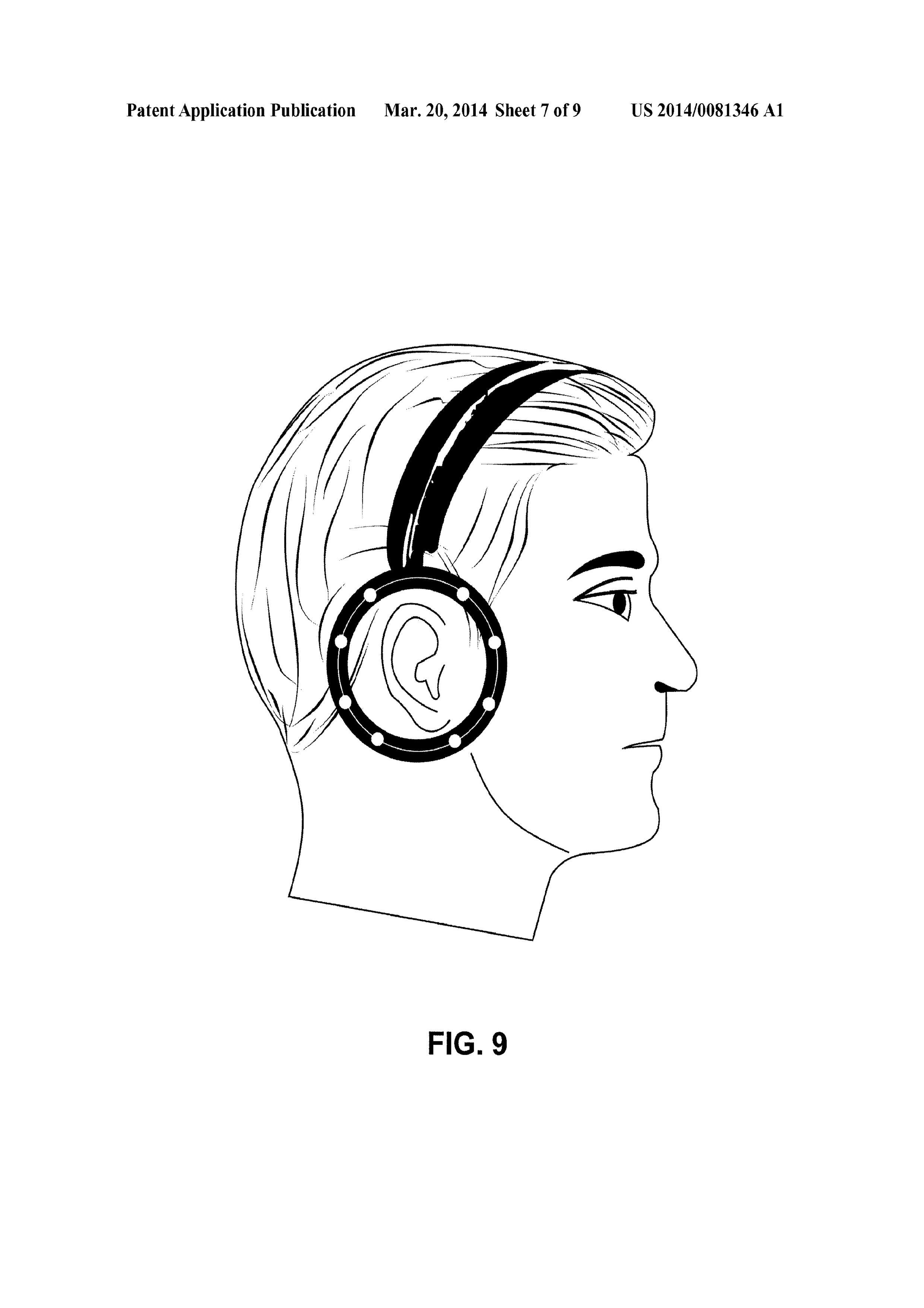
[0140] For this type of stimuli, the electrode system developed consists of a diadem placed on the head (see FIG. 9) in the same manner than an old headphone system. The end part of this diadem completely surrounds the ear's pinna. The diadem has a set of non-polarizable silver chloride electrodes adhered to this part (white circles). 5-mm diameter electrodes are used in aspects of the present invention, but there can be multiple variables of these electrodes.
[0141] The shape, number, size and all other characteristics of the electrodes are to variable and have the purpose of stimulating diverse areas of the periauricular region in a selective manner, reaching all the structures of the vestibule and inducing complex movement sensations in this manner, thus being able to stabilize the subject's position with the purpose of activating the vestibular system indirectly.
[0142] The electrode system is connected to the output of the conditioning system, which is, in turn, controlled by the microprocessor receiving the input from the MEMS and it process the information using the mathematical model of the vestibular function, thus generating a specific electrical stimulation pattern that is a function of the movement of the subject's head.
[0143] According to various aspects, the electrode system may be monitored via a combination of hardware and software combination. For example, FIG. 10 presents an example system diagram of various hardware components and other features, for use in accordance with an aspect of the present invention. The present invention may be implemented using hardware, software, or a combination thereof and may be implemented in one or more computer systems or other processing systems. In one aspect, the invention is directed toward one or more computer systems capable of carrying out the functionality described herein. An example of such a computer system 900 is shown in FIG. 10.
[0144] Computer system 900 includes one or more processors, such as processor 904. The processor 904 is connected to a communication infrastructure 906 (e.g., a communications bus, cross-over bar, or network). Various software aspects are described in terms of this example computer system. After reading this description, it will become apparent to a person skilled in the relevant art(s) how to implement the invention using other computer systems and/or architectures.
[0145] Computer system 900 can include a display interface 902 that forwards graphics, text, and other data from the communication infrastructure 906 (or from a frame buffer not shown) for display on a display unit 930. Computer system 900 also includes a main memory 908, preferably random access memory (RAM), and may also include a secondary memory 910. The secondary memory 910 may include, for example, a hard disk drive 912 and/or a removable storage drive 914, representing a floppy disk drive, a magnetic tape drive, an optical disk drive, etc. The removable storage drive 914 reads from and/or writes to a removable storage unit 918 in a well-known manner. Removable storage unit 918, represents a floppy disk, magnetic tape, optical disk, etc., which is read by and written to removable storage drive 914. As will be appreciated, the removable storage unit 918 includes a computer usable storage medium having stored therein computer software and/or data.
[0146] In alternative aspects, secondary memory 910 may include other similar devices for allowing computer programs or other instructions to be loaded into computer system 900. Such devices may include, for example, a removable storage unit 922 and an interface 920. Examples of such may include a program cartridge and cartridge interface (such as that found in video game devices), a removable memory chip (such as an erasable programmable read only memory (EPROM), or programmable read only memory (PROM)) and associated socket, and other removable storage units 922 and interfaces 920, which allow software and data to be transferred from the removable storage unit 922 to computer system 900.
[0147] Computer system 900 may also include a communications interface 924. Communications interface 924 allows software and data to be transferred between computer system 900 and external devices. Examples of communications interface 924 may include a modem, a network interface (such as an Ethernet card), a communications port, a Personal Computer Memory Card International Association (PCMCIA) slot and card, etc. Software and data transferred via communications interface 924 are in the form of signals 928, which may be electronic, electromagnetic, optical or other signals capable of being received by communications interface 924. These signals 928 are provided to communications interface 924 via a communications path (e.g., channel) 926. This path 926 carries signals 928 and may be implemented using wire or cable, fiber optics, a telephone line, a cellular link, a radio frequency (RF) link and/or other communications channels. In this document, the terms “computer program medium” and “computer usable medium” are used to refer generally to media such as a removable storage drive 980, a hard disk installed in hard disk drive 970, and signals 928. These computer program products provide software to the computer system 900. The invention is directed to such computer program products.
[0148] Computer programs (also referred to as computer control logic) are stored in main memory 908 and/or secondary memory 910. Computer programs may also be received via communications interface 924. Such computer programs, when executed, enable the computer system 900 to perform the features of the present invention, as discussed herein. In particular, the computer programs, when executed, enable the processor 910 to perform the features of the present invention. Accordingly, such computer programs represent controllers of the computer system 900.
[0149] In an aspect where the invention is implemented using software, the software may be stored in a computer program product and loaded into computer system 900 using removable storage drive 914, hard drive 912, or communications interface 920. The control logic (software), when executed by the processor 904, causes the processor 904 to perform the functions of the invention as described herein. In another aspect, the invention is implemented primarily in hardware using, for example, hardware components, such as application specific integrated circuits (ASICs). Implementation of the hardware state machine so as to perform the functions described herein will be apparent to persons skilled in the relevant art(s).
[0150] In yet another aspect, the invention is implemented using a combination of both hardware and software.
[0151] FIG. 11 is a block diagram of various example system components, in accordance with an aspect of the present invention. FIG. 11 shows a communication system 1000 usable in accordance with the present invention. The communication system 1000 may include one or more accessors 1062 (also referred to interchangeably herein as one or more “users”) and a terminal 1066. According to various aspects, the terminal 1066 may include a processor and one or more electrode system such as the electrode system described above. In one aspect, data for use in accordance with the present invention is, for example, input and/or accessed by accessors 1062 via terminal 1066, such as a personal computer (PC), minicomputer, mainframe computer, microcomputer, telephonic device, or wireless devices, such as a personal digital assistant (“PDA”) or a hand-held wireless device, such device optionally further including, for example, one or more sensing devices and/or connections to such devices (e.g., an electrode system), coupled to a server 1043, such as a PC, minicomputer, mainframe computer, microcomputer, or other device having a processor and a repository for data and/or connection to a repository for data, via, for example, a network 1044, such as the Internet or an intranet, and couplings 1046 and 1064. The couplings 1046 and 1064 include, for example, wired, wireless, or fiberoptic links.
[0152] Even though aspects of the invention have been described by referring to various aspects of the present invention and examples regarding a micro-electro-mechanical system simulating the vestibular function, the invention's scope and spirit includes the incorporation or its use with any system and/or appropriate mechanical device. Therefore, it must be understood that numerous and varied modifications can be carried out without departing from the spirit of the invention.
Public University with 527 full time teachers, recognized by the national system of researchers (S.N.I.), with a large contribution from documents of scientific divulgation in diverse areas of knowledge and presentation of patent documents, which occupies the third place in the ranking of universities in Mexico with the largest number of patent applications
Create your free account to connect with Benemérita Universidad Autónoma de Puebla and thousands of other innovative organizations and professionals worldwide
Send a request for information
to Benemérita Universidad Autónoma de Puebla
Technology Offers on Innoget are directly posted
and managed by its members as well as evaluation of requests for information. Innoget is the trusted open innovation and science network aimed at directly connect industry needs with professionals online.
Need help requesting additional information or have questions regarding this Technology Offer?
Contact Innoget support